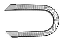
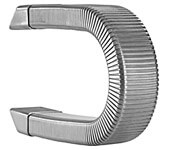
STABIFLEX cable conduits are moving cable carriers which have proved successful in a wide range of applications in machine tools and machining centers. The main feature of this closed cable carrier is that through the fitting of a steel band to one of the four sides the flexible conduit can only bend in the one direction where the steel band is situated. In all other directions of movement the conduit remains stable.
- STABIFLEX cable conduits are resistant against all coolants and lubricants normally used in the machine tool industry.Three qualities are available (depending on the traverse speed):
- Quality N
Fitted with a steel band for speeds of v 20 m/min. - Quality G
Featuring a steel band fixed with special glue for speeds of v = 20-50m/min. - Quality K
Featuring a synthetic band fixed with special glue for speeds of v = 50 m/min.
If no traverse speed is indicated, we automatically choose the N quality.
- Quality N
- To obtain the shortest possible length, it is recommended to have the fixed connection at the mid-point of the stroke.
- When choosing the required type of STABIFLEX, an allowance of at least 10% per cable should be considered.
- Made of zinc plated sheet steel.
- To determine the bending radius (KR), multiply the outer diameter of the cables to be installed by a factor of 8 to 10. However, the minimum bending radius indicated by the cable manu-facturers is the main criterion.
- Mounting flanges are welded on both ends of the cable conduit.
- In accordance with safety
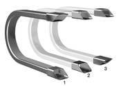
regulations, electrical continuity is maintained between the flanges and the metal conduit. The cables are loosely guided in the STABIFLEX and fastened at the moving and fixed end. - A tandem version (two or three metal conduits on one steel band) can be supplied to guide various cables and hoses in separate compartments.
- To ensure long-term functioning, it is necessary to guide the STABIFLEX in support angles or in a channel the length of which should be approx. ½ stroke.
Technical Details
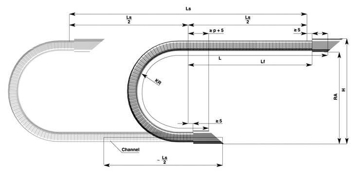
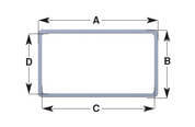
Legend
A x B = STABIFLEX – outside cross-section
C x D = STABIFLEX – inside cross-section
Lf = Unsupported length
L = STABIFLEX length
Ls = Travel
KR = Bending radius (Tolerance -20%)
H = Mounting height
p = Depth of conduit fitted in the flange
RA = Minimum height of support
Notes
L = Ls/2 + 4KR + 50 (mm) *
L = Ls/2 + πKR + 2p + 10 (mm) **
* Approximate value
** Formula used to calculate the precise length (rounded off to 10 mm)
Functions
Flange Arrangements
Hose Cross Section
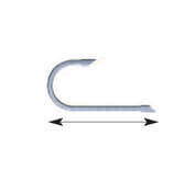
Direction of Operation
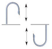
Vertical Standing (left)
Vertical Suspended (right)
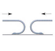
Top View
Technical Details
| STABIFLEX Type |
A | B | C | D | P | KR | RA (incl. pre-load) |
H (incl. pre-load) |
L fmax |
L s without support |
L s with support |
Weight Hose kg/m |
Weight Flanges kg/Paar |
|---|---|---|---|---|---|---|---|---|---|---|---|---|---|
| 0.0 | 30 | 20 | 26 | 16 | 25 | 55 | 120 | 144 | 1000 | 2000 | 4000 | ~ 0.6 | ~ |
| 1.0 | 50 | 30 | 43 | 23 | 30 | 72 110 165 |
160 235 345 |
194 269 379 |
1500 | 3000 | 6000 | ~ 1.25 | ~ 0.2 |
| 1.1 | 50 | 50 | 45 | 45 | 50 | 110 | 240 | 294 | 2000 | 4000 | 8000 | ~ 1.7 | ~ 0.3 |
| 2.0 | 80 | 45 | 73 | 38 | 45 | 110 220 275 |
240 460 570 |
290 510 620 |
2000 | 4000 | 8000 | ~ 2.25 | ~ 0.5 |
| 2.1 | 85 | 60 | 80 | 55 | 65 | 165 | 350 | 415 | 2500 | 5000 | 10,000 | ~ 2.4 | ~ 0.6 |
| 2.2 | 95 | 50 | 90 | 45 | 60 | 130 | 280 | 335 | 2000 | 4000 | 8000 | ~ 2.9 | ~ 0.6 |
| 3.0 | 110 | 60 | 102 | 52 | 60 | 155 250 330 |
335 525 685 |
400 590 750 |
2500 | 5000 | 10.000 | ~ 3.6 | ~ 1.0 |
| 3.1 | 115 | 80 | 109 | 74 | 80 | 220 | 465 | 550 | 2500 | 5000 | 10.000 | ~ 3.8 | ~ 1.2 |
| 4.0 | 170 | 80 | 162 | 72 | 80 | 205 | 435 | 520 | 2500 | 5000 | 10.000 | ~ 5.6 | ~ 1.7 |
| 4.1 | 175 | 110 | 167 | 102 | 80 | 285 | 600 | 717 | 2500 | 5000 | 10.000 | ~ 5.8 | ~ 3.9 |